EN
EN
 Deutsch
 Italiano
 Español
 Français
 日本語
日本語
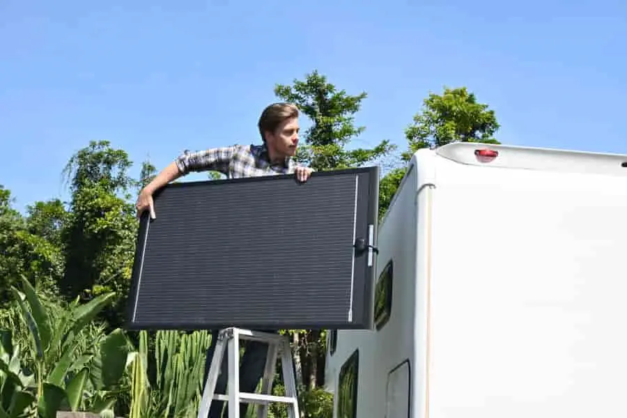
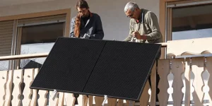
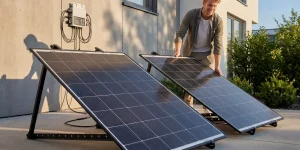
If you’re wiring RV SOLAR PANELS in a European winter, voltage windows and cable loss matter more than anything. This step-by-step solar panel wiring diagram guide shows you how to wire a 3S-1P 540 W solar panel array that works with the EcoFlow Delta Pro. Your solar panel system for RV will keep charging even when it’s –10 °C. You’ll get a PDF of the solar panel wiring diagram, a voltage-at-low-temperature check, line and fuse sizing, a 15-minute install GIF, and a 7-day Norway log. This setup works whether you have a simple RV solar panel or a full RV solar panel kit with a battery and inverter.
Q:Should I wire panels on an RV in Europe in December in series or parallel?
A: For a 3-panel array, use series: 3 × ~36 V Voc = total Voc < 120 V at –10 °C, which is higher than Delta Pro’s ~80 V start threshold. Use parallel only for two or fewer panels that are heavily shaded.
Solar panel diagram and solar wiring diagram are two keywords that come to mind.
Why a lot of "100 W standard panels" don't work well in the winter
As the temperature drops, the Voc goes up (~+0.3%/°C). You need to pass the MPPT start voltage but not go over the absolute max. input.
Not enough in series means it won’t start; too many means Voc is too high when it’s cold.
RV shading is hard to understand. Parallel shading helps shade but lowers the array voltage, which raises loss. 3S often wins when it comes to RVs with solar panels that want portable power stations.
Table (copy-ready)
| Scenario | Std. 100 W (Voc 22 V) ×3 in series | Custom 180 W (Voc 42 V) ×3 in series |
|---|---|---|
| 25 °C Voc | 66 V | 126 V → over limit |
| –10 °C Voc | 22×1.15×3 ≈ 76 V | 42×1.15×3 ≈ 145 V → over limit |
| After cold derating | — | 42×1.12×3 = 141 V → minus one cell-strip → 39×1.12×3 = 131 V still high |
| Final plan | — | 36×1.12×3 = 121 V ✅ |
Takeaway: Change the design to 60 cells (Voc≈36 V). At –10 °C, 3S stays below the hardware limit with about 9% headroom, which is perfect for RV solar panel kit designs.
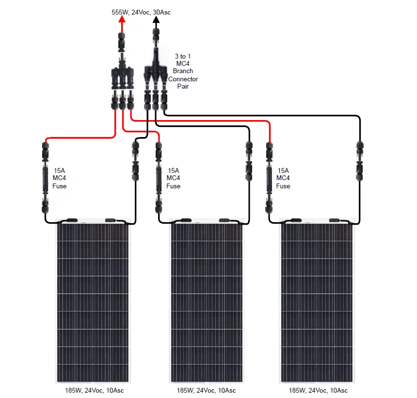
Wiring Diagram: 3S-1P 540 W “Plug-and-Play” Solar Panel Wiring Diagram
Panel1 to Panel2 to Panel3 (MC4 F→M) in a series
Add a 5 m MC4 extension with 10 AWG (≈6 mm²) wire.
+ pole inline 15 A MC4 fuse (CE)
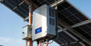
Link the EcoFlow MC4 to the XT60 lead
MPPT reads 100–115 V / ~4.8 A ≈ 480 W (Oslo, 11:00, December)
Bill of Materials (CE/TÜV)
| Item | Qty | Link |
|---|---|---|
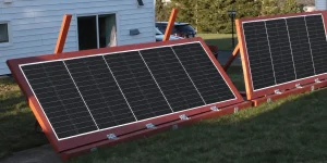
| Custom 180 W semi-flex (60 cells, 595×995 mm) | 3 | Product |
| MC4 10 AWG extension 5 m | 1 pair | Accessory |
| MC4 15 A inline fuse | 1 | Accessory |
| EcoFlow MC4→XT60 cable | 1 | OEM |
| No-drill SS brackets 595 mm | 6 | Accessory |
If your rv solar panel kit with battery and inverter exceeds 600 W or cable run >8 m, consider 8 AWG to reduce drop.
Solar Panel Wiring Diagram:15-Minute Install
Clean roof → apply no-drill brackets (3M VHB + screws) → follow solar panel diagram to click MC4 → fully seat fuse → power-up self-test → log output in app.

Top 3 Mistakes (and fixes)
3×100 W standard panels: Voc≈76 V at –10 °C and less than 80 V at start; no charge
Use 3×36 V-Voc custom in series; only use 4S in very cold weather if the absolute maximum allows it.
When you connect four panels in parallel without branch fuses, the current goes backward and burns the MC4.
Use a compliant combiner for RVs with solar panels and fuse each branch.
6 mm² over 10 m → about 8% less (500 W to 460 W)
Prefer shorter runs, thicker cable (8 AWG), and higher voltage (series).
Checklists for Engineers (for pros)
The voc temp coefficient is about +0.3% per °C (–10 °C vs. 25 °C ≈ +10.5%).
Check Vstart and MPPT tracking range in the start window.
Absolute max: check Vmax on a cold day (–10 to –20 °C)
Cable sizing: for an RV solar panel kit, the drop should be less than 3%.
Protection: branch fuses for parallel circuits and a DC breaker on the main circuit
Check +/- for polarity and bonding; anti-corrosion and strain relief
Before turning on the power, check the Voc/polarity; after turning on the power, check the V/A/W.
Next Steps (CTA)
Send roof L×W and obstacles → CAD layout + quote in 3 h
Stock ships in 72 h, EU delivery 4–6 days
DM WhatsApp → free 15 A fuse with your rv solar panel kit
FAQ
Q1: Is there a wiring diagram for all RVs’ solar panels?
A: No. Always check the Voc and MPPT limits first, then figure out how long and how much drop your solar panel system needs for RV.
Q2: Do I have to parallel when there is a lot of shade?
A: Not always. For portable power stations, 3S usually works better with Vstart. If you do parallel, make sure to fuse each branch.
Q3: What is a quick rule for sizing cables?
A: Target drop of less than 3%: higher voltage (series), thicker cable, and shorter run.