Why this guide? Off-the-shelf RV “solar system” rarely fit real roofs, curved surfaces, strict weight limits, or regional electrical rules. This article walks you—OEM engineers, pro upfitters, and serious travelers—through a practical sizing method, shade-resilient design, BOM templates, and install checks so you can land on a solution that actually works on the road.
Who actually needs a custom system (not a kit)?
Short answer: If you care about fit, finish, output stability, and compliance, you need custom.
Tight space & weight limits: Lightweight or curved roofs, low wind noise targets, stealth installs.
Complex roofs: Antennas, A/C units, racks, beams—i.e., inevitable partial shade zones.
EU vs North America: Different wiring practices, labeling, protection devices, and acceptance tests.
OEM / integrators: You need engineering drawings, a predictable BOM, maintenance docs, and expansion paths.
When flexible/low-profile panels help
Roof load < 10–12 kg/m², noticeable curvature, or strict height/aero constraints.
You want clean aesthetics with back-exit leads and minimal standoffs.
You must route around shadows with segmented strings and multiple MPPTs.
Call to action: Send us your vehicle model, roof photos, and a simple load list—we’ll return a 1:1 engineering pre-check and a preliminary BOM.
Size your system in 3 steps (fast + accurate enough for scoping)
Use this for scoping and sanity checks. Final designs should be validated with local codes and real measurements.
1) Make a load list → daily energy (Wh/day)
Quick example (partial):
Compressor fridge: 60 W × 24 h × duty 0.3 ≈ 432 Wh
Lights: 20 W × 4 h = 80 Wh
Roof fan: 24 W × 6 h = 144 Wh
Laptop: 65 W × 3 h = 195 Wh
Typical total: ~1,200–1,800 Wh/day for a modern camper with reasonable usage.
2) Battery capacity (with autonomy, DoD, margin)
Battery Wh = (Wh_day × Days of autonomy / DoD) × (1 + margin)
Convert to Ah for 12 V: Ah = Battery Wh / 12
Example: Wh_day = 1,600; autonomy = 1.5 days; DoD = 0.8 (LiFePO₄); margin = 0.15 →
Battery Wh ≈ 3,450 Wh → at 12 V ≈ 288 Ah → recommend 12 V 300 Ah LiFePO₄.
3) PV array power (consider HSP & losses)
P_PV = (Wh_day * (1 + seasonal/uncertainty)) / (HSP * eta_sys)
Seasonal/uncertainty: 0.15–0.30
System efficiency ηsys\eta_{sys}ηsys: 0.70–0.80 (MPPT, temperature, wiring)
Example: 1,600 Wh/day, HSP = 4.0 (EU summer mid-lat), margin = 0.2, η = 0.75 →
PPV≈19203.0≈640 WP_{PV} \approx \frac{1920}{3.0} \approx \mathbf{640\,W}PPV≈3.01920≈640W.
Winter/high latitude (HSP = 2.5): target 900–1,000 W + alternator/DC-DC or shore-power assist.
Takeaways
Summer “just enough,” winter “hybrid.” Plan for shore/alternator assist off-season.
If you regularly boondock: bigger battery + two MPPT inputs beats one giant string.
System selection & sample BOM
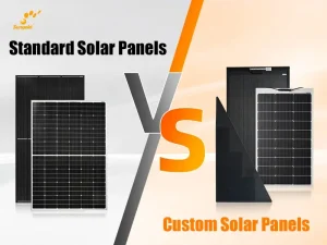
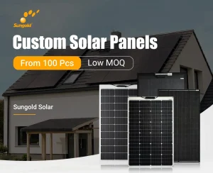
Panel choice: glass vs flexible
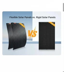
Glass: best long-term durability and cleaning, but heavier and taller (noise/drag).
Flexible/low-profile: lighter, curved-roof friendly, cleaner look; demands good thermal path and edge sealing to extend life.
Controllers & stringing (MPPT is not optional)
Prefer multiple independent MPPTs (2–3 inputs) when shade/roof segments differ.
Size current:
IMPPT≥PPVVbat(min)×1.25I_{MPPT} \ge \frac{P_{PV}}{V_{bat(min)}}\times 1.25IMPPT≥Vbat(min)PPV×1.25
Shade-heavy roofs: more parallel, fewer series modules; isolate segments per MPPT.
Batteries: LiFePO₄ vs AGM
LiFePO₄: higher cycle life, deeper usable capacity, lighter; needs BMS & correct charge profile.
AGM: lower entry cost; heavier, lower energy density/cycle life.
Inverter, wiring, and protection
Inverter continuous ≥ 1.25× your peak running load; check idle draw.
Keep DC voltage drop <3% on critical runs; every branch gets proper OCPD (fuse/breaker).
Grounding/bonding, strain relief, glands, and labels matter.
Sample BOM (edit to your project)
Sample BOM (edit to your project)
| Component | Spec suggestion | Qty | Selection notes | Install notes | Compliance notes |
|---|---|---|---|---|---|
| Low-profile/flexible PV | 200–300 W per sheet; back-exit leads | 3–4 | Segmented strings, shade-tolerant layout | Edge sealing, small air gap for heat | EMC, bonding |
| Glass PV (option) | 350–450 W per module | 2–3 | Higher durability | Low-rise mounts to cut noise/drag | Mechanical strength |
| MPPT controller | 30–60 A × 2–3 inputs | 2–3 | Independent trackers | Short DC runs, heat sinking | Polarity/OCPD |
| LiFePO₄ battery | 12 V 300–400 Ah or 24 V 200 Ah | 1 set | BMS, low-temp charging logic | Secure mount, vent space | Clearances/labels |
| DC-DC alternator charger | 30–60 A | 1 | Smart alternator compatible | IGN trigger wiring | Cable gauge/fuse |
| Pure sine inverter | 1.5–2.5 kW | 1 | 2× surge, low idle | Remote switch if hidden | Ground/ELCI/GFCI |
| Cables & protection | As per run length & amps | — | <3% drop targets | Drip loops, abrasion sleeves |
Cable gauge quick guide (12 V side, <3% drop)
Cable gauge quick guide (12 V side, <3% drop)
| One-way length | 10 A | 20 A | 40 A | 60 A |
|---|---|---|---|---|
| ≤2 m | 4 mm² | 6 mm² | 10 mm² | 16 mm² |
| 2–4 m | 6 mm² | 10 mm² | 16 mm² | 25 mm² |
| 4–6 m | 10 mm² | 16 mm² | 25 mm² | 35 mm² |
(For 24 V, current halves for the same power; verify with a voltage-drop calculator.)
Designing for shade and heat (the real-world deal)
Problem: RV roofs throw transient shadows (antennas, racks, beams) and trap heat. A single long series string can collapse when any cell string is shaded.
Better pattern
Multiple MPPTs: Put each roof zone on its own tracker so localized shade doesn’t drag the whole array.
Segmented strings + bypass: Prefer panels and layouts that split strings and provide robust bypassing.
Thermal design: Preserve a slim ventilation corridor, mount controllers/inverters with independent airflow, and avoid stacking heat sources.
Low-profile routing: Back-exit leads, gland fittings, drip loops, and abrasion protection reduce failures.
On curved or tight roofs, a flexible, segmented array plus 2–3 MPPTs typically yields the most stable day-long output.
EU vs North America: practical compliance notes (informational, not legal advice)
EU: See IEC 60364-7-721 / country adoptions (e.g., VDE 0100-721 in Germany) for leisure vehicles; EMC often references ECE R10.
North America: See NEC Article 551 (Recreational Vehicles and RV Parks) and CSA C22.1 sections.
Common threads: Correct over-current protection, isolation/grounding, labeled disconnects, proper penetrations and grommets, cable sizing for temperature and bundling, documentation on handover.
Always validate with a licensed professional in your jurisdiction. Document everything.
From survey to handover: a reliable install flow
Measure & confirm
Roof dimensions/curvature, obstacles; photos + simple sketches; load list and usage pattern.Routing & waterproofing
Shortest DC runs, proper supports, abrasion sleeves; cable glands + drip loops; sealed penetrations.Mechanical & safety
Flex panels need clean substrate and full-surface adhesion or suitable backing; glass modules need verified mount strength and wind loading calcs.Test & document
Polarity, insulation, voltage-drop, functional tests; hand over wiring diagram, parameters, maintenance schedule, and basic troubleshooting.
FAQ
Q1. How do I keep power in winter or cloudy spells?
Upsize PV if the roof allows and plan hybrid charging: alternator (DC-DC), shore, and optional portable panels.
Q2. Do flexible panels always die sooner?
Quality and install matter. Use segmented designs, ensure thermal path and edge sealing, avoid foot traffic, and keep them clean.
Q3. 12 V or 24 V?
Above ~1.5–2 kW of inverter load or heavy DC currents, 24 V reduces current and voltage drop. For legacy 12 V appliances, stay 12 V or add DC-DC rails.
Q4. Will alternator charging fight the solar controller?
A proper DC-DC charger coordinates charging profiles. Parallel sources are common in modern RVs.
Q5. Are multiple MPPTs worth the cost?
On shaded or multi-zone roofs, yes. They prevent one shaded area from throttling the whole array.
Q6. How big should the inverter be?
Sum your simultaneous AC loads and add ~25% headroom; check startup surges (some devices need 2×+ for a second or two).
Q7. Do I need a grid-tie inverter for campsites?
RV systems are typically off-grid. If your site offers hookups, you use a charger/transfer solution—not grid-feeding.
Q8. How do I choose cable size?
Target <3% voltage drop on critical runs. Consider ambient temperature, bundling, and route length; protect every branch with OCPD.
Q9. Does anti-shade stringing lose efficiency?
Segmentation and bypassing add negligible losses but protect output when shade hits part of the array.
Q10. What should I test before handover?
Polarity, insulation resistance, voltage under load, controller setpoints, and inverter function. Document the results.
Your next step (CTA)
Get a tailored RV power plan.
Upload your vehicle model, roof photos, and a simple load list (download our template). Our engineers will return:
A capacity estimate and PV layout idea
A draft BOM with controller/battery/inverter sizing
Wiring and protection notes, plus an installation checklist
Prefer to self-scope first? Download the “RV System Checklist (PDF)” with formulas, a sizing table, and a printable roof-measurement sheet.