EN
EN
 Deutsch
 Italiano
 Español
 Français
 日本語
日本語

What Does "Bend Limit" Actually Mean on a Flexible Solar Panel?
How much can flexible solar panels bend is a question that gets two very different answers depending on who you ask: a marketer or an engineer. This guide gives you the engineering answer.
- Definition
- The bend limit of a flexible solar panel is the minimum radius — measured in millimeters along a defined bending axis — at which the laminate can be curved without exceeding the mechanical strain tolerance of the silicon cells, interconnect ribbons, and encapsulant. It is a static measurement. It does not describe how many times the panel can flex under load, or how it behaves under road or wave vibration over years of service.
That second sentence is the part most product pages skip. We will come back to it at length in the exclusive insight section below — because it is where most installation problems actually originate.
What Is the Difference Between "248° Bendable" and Minimum Bend Radius?
These two numbers describe different things. Mixing them up is the most common spec-reading mistake I see among buyers.
The "degrees" figure: a mounting geometry descriptor
When a panel is advertised as "bendable up to 248°" or "250°," that number describes the arc angle the panel can subtend across a curved surface — typically a rounded van roof or barrel-shaped RV top. It is a statement about mounting geometry, not about material strain limit. A panel described as "248° bendable" is being installed across a gentle, consistent curve — not folded or kinked.
Minimum bend radius: the engineering limit
Minimum bend radius (R_min) is the engineering constraint. It is the smallest circle radius the laminate can conform to before the inner cell layer experiences tensile strain above its fracture threshold. Most monocrystalline flexible panels publish R_min values between 200 mm and 400 mm. Some semi-flexible panels specify 20–40 cm (200–400 mm, same range). CIGS thin-film designs can go tighter because their active layer is a different material entirely.
| Figure you see | What it describes | Who uses it | What to do with it |
|---|---|---|---|
| "248° bendable" / "250° bendable" | Maximum arc angle across a curved mounting surface | Consumer electronics listings, retail product pages | Confirms the panel can follow a gently curved roof — does not define safe curve tightness |
| Minimum bend radius (mm or cm) | Tightest safe curve along the specified bending axis before cell damage risk | Engineering datasheets, OEM spec sheets | Measure your installation surface — require a confirmed R larger than this value, with margin |
| Bend axis (long edge / short edge) | Direction of curvature the spec applies to | Technical datasheets | Install the panel in the axis direction specified; bending across the wrong axis may invalidate the spec entirely |
| Flex cycle count (e.g. "1,000+ flex cycles") | Number of repeated bend-and-release cycles at a specific radius before measurable degradation | Premium OEM documentation | Relevant only if the panel will be repeatedly flexed (rollable, portable); irrelevant for permanent installs |
How Much Can Flexible Solar Panels Bend — By Cell Technology?
The answer is technology-dependent. Here is the honest breakdown across the three main flexible panel designs.
| Panel type | Typical R_min | Why that limit exists | Common applications |
|---|---|---|---|
| Monocrystalline silicon laminate (most common) | 200–400 mm | Silicon cells are brittle; interconnect ribbons fracture under higher strain; encapsulant limits strain transfer | RV roofs, van builds, boat decks with gentle curves |
| Semi-flexible with fiberglass substrate | 200–400 mm (similar) | Fiberglass backing adds stiffness that distributes bending stress; limits tighter radii but improves durability over time | RV and camper applications requiring more impact resistance |
| CIGS thin-film laminate | Can be significantly tighter; some designs allow very tight wrap radii | Copper-indium-gallium-selenide active layer is deposited as a continuous thin film — no discrete silicon wafers to crack | Curved architectural surfaces, specialty vehicles, wearable applications |
| Rollable / ultra-thin polymer film | Can roll around a small cylinder when designed for it | Organic or perovskite-based cells on flexible polymer substrate; much lower efficiency but extreme form-factor flexibility | Portable chargers, niche IoT and military applications — not mainstream RV or marine |
I've found that the monocrystalline laminate column is where almost all RV and marine buyers land — and where almost all installation-related failures originate when bend limits are ignored. The CIGS column is genuinely more flexible, but efficiency trade-offs and procurement complexity mean most mobile-build customers don't use it.
A practical installation check before ordering
Take a flexible measuring tape and hold it against your roof's most pronounced curve. Note the chord length (straight-line distance between two points) and the sag height (how far the curve rises above that chord). From those two numbers you can calculate approximate radius. If that radius is larger than the panel's published R_min — with at least a 20–25% safety margin — you are within safe installation territory.
Why Static Bend Radius and Dynamic Flex Are Two Different Problems
This is the section most product guides skip entirely. It is also where the gap between a successful installation and an early failure is widest.
The static bend radius is measured once, in a lab, at room temperature
When a manufacturer publishes R_min = 250 mm, that number comes from a single-axis static bend test — the panel is curved to that radius, held, and then inspected for cell cracks and power loss. The test is standardized and repeatable. IEC 61215-1-1:2021, which covers crystalline silicon PV module design qualification and includes test methods for flexible-type module constructions, defines bending tests (MQT 22 series) that measure post-bend performance.[1]
What that test does not replicate: a van traveling 30,000 miles a year over mixed road surfaces, generating continuous low-amplitude vibration at the resonant frequencies of its body panels. Or a sailboat pitching in moderate swells, flexing the coach roof 0.3 mm every four seconds for a 10-day passage.
Micro-cracking from vibration is cumulative and invisible
Silicon cells do not snap cleanly under vibration. They develop micro-cracks — hairline fractures at cell edges and through solder joints — that progress slowly. Early-stage micro-cracking rarely triggers a visible symptom. The first sign is usually a measurement showing lower short-circuit current (Isc) from one panel versus its neighbors on a clear day. By then the damage is done.
I've seen this on fleet builds where the panels were spec-compliant on day one — static radius within limit, correct adhesive, clean installation. By month eight, one panel in a four-panel array was producing noticeably less. EL imaging (electroluminescence testing) showed a classic micro-crack pattern radiating from a corner. The root cause was a substrate resonance: the aluminum roof skin flexed slightly at highway speed, and the corner of the laminate experienced repeated micro-deflection beyond the manufacturer's static spec. A foam riser under the panel corners would likely have decoupled the vibration path. It didn't matter that the static bend spec was respected; the dynamic problem was never considered.
What does IEC testing actually verify?
IEC qualification tests like those described in the 61215 series confirm that a module can survive defined stress sequences without specified degradation — thermal cycling, humidity-freeze, damp heat, and for flexible types, bending sequences. This is a credible baseline for material durability. It is not a road test. It does not replicate multi-year real-world vibration on a vehicle platform. The standard itself does not claim that it does.
The useful takeaway: IEC certification tells you the module passed a defined set of conditions. It tells you nothing about the resonant behavior of your specific roof substrate under your specific driving pattern. Those are your engineering variables to manage.
How Does Panel Size, Cell Layout, and Busbar Routing Change Bendability?
Two panels can have the same published R_min and behave very differently under the same installation conditions. The reason is internal geometry.
Bending axis matters: long edge versus short edge
Most monocrystalline laminates are rectangular, with cells arranged in columns. Bending along the long axis curves each cell column into an arc — stressing the cell edges running parallel to that axis. Bending along the short axis stresses the inter-cell gap and interconnect ribbons running across columns. These are different stress states, and many datasheets specify R_min for one axis only. If yours doesn't specify which axis, ask before you install.
Corner stress concentration
When a panel conforms to a convex surface (a rounded van roof, for example), the geometric center conforms smoothly. The corners, however, experience compound bending — curvature in two directions simultaneously if the panel is not perfectly aligned with the roof's principal axis. Corner cells are statistically the first to show micro-cracks in post-installation EL analysis. If your panel has bypass diodes arranged by column, corner failures eventually show up as full column output losses during partial shade.
Busbar routing and interconnect ribbon geometry
The metal busbar strips and tabbing ribbons connecting cells are the mechanical fuse in the laminate. They are designed to handle bending along the approved axis with a defined stress distribution. Changes to busbar count (3BB, 5BB, 9BB, 16BB designs), ribbon width, and cell shingling all affect how strain is distributed. A panel with closely-spaced half-cut cells and narrow ribbons will generally distribute bend stress more evenly than a full-cell design with wide busbars — but only along the designed bend axis.
How Do Temperature and Adhesive Choice Interact With Bend Limits?
Bending and heat are not independent variables in a real installation. They interact, and the combination produces outcomes that neither spec handles alone.
EVA encapsulant softens above approximately 60–70°C. On a sun-heated metal roof in summer, the laminate's effective stiffness decreases. A panel that was installed at the acceptable limit of its R_min may creep slightly tighter over repeated heat cycles — not dramatically, but enough to contribute to long-term fatigue at the edge seal.
Adhesive systems matter too. A high-expansion-coefficient adhesive bonding a low-expansion-coefficient panel to a high-expansion-coefficient aluminum substrate will cyclically stress the laminate edges every day as temperature swings from night to peak afternoon. If the panel is also at the edge of its bend spec, that thermal strain adds to the mechanical strain the cells already experience from curvature. The two problems stack.
I've written about the heat side of this equation in the first article in this series — Are flexible solar panels worth it? — which covers air gap, operating temperature, and their effect on both output and longevity. Read them together if you are planning a real install, because the bend spec and the thermal spec are never truly independent.
What Are the Real-World Applications Where Bend Limits Matter Most?
Different platforms create different bending challenges. Here is what actually matters by surface type.
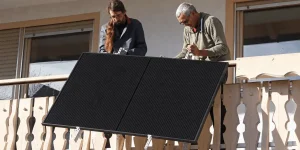
Rounded RV and camper van roofs
Most production RV roof profiles have radii of curvature between 600 mm and 2,000 mm — well within R_min for most monocrystalline laminates. The bending constraint here is rarely the radius itself; it is the compound curvature at the roof-to-sidewall transition and the substrate vibration discussed above. Design check: confirm the roof's flattest axis, align the panel's specified bending axis with that direction, and isolate from vibration with appropriate spacers.
Sailboat and yacht decks
Yacht coach roofs and bimini tops often have tighter radii than RV roofs, and they introduce saltwater exposure and additional UV. The bending check is more critical here: measure the deck curve specifically at the proposed panel location, not a general estimate. Bow and stern areas typically have tighter curves than the central deck. Marine-grade IP67 connectors are a separate requirement from the bend limit but equally non-negotiable.
Architectural curved surfaces
Building-integrated applications — curved canopies, barrel vaults, folded roof elements — may require CIGS or specialized thin-film laminates if the design radius is below 200 mm. Monocrystalline laminates are unlikely to be appropriate for true architectural tight-curve applications without custom engineering review.
Portable and rollable use cases
If the panel is being rolled for transport and unrolled for deployment, the flex cycle count matters as much as R_min. Panels designed for periodic roll-and-deploy use are a specific product category — not a standard monocrystalline laminate with a low R_min. Confirm the product is designed for repeated flexing, not just a single installation curvature.
What Mistakes Do Installers Make Around Bend Radius?
These are the five errors I see most often, ranked by how invisible the damage is until it is too late.
- Cold-temperature bending. Attempting to conform a panel to a curved surface at temperatures below 10°C. Most encapsulants are significantly stiffer in cold conditions, and the cell stack is more brittle. If you are doing a winter van build in a cold garage, warm the panels to room temperature before conforming them to the roof curve.
- Two-point bending instead of distributed support. Resting the center of the panel on a roof peak and pressing both ends down creates a sharp bend at the contact point — far tighter than the overall roof radius. Use distributed adhesive or spacers that follow the entire panel length, not just two endpoints.
- Re-bending after adhesive cure. Attempting to adjust the curvature after the bonding adhesive has partially or fully cured. Once the adhesive sets, mechanical resistance to curvature change is borne entirely by the laminate — not by any installer muscle.
- Ignoring the long-edge vs short-edge axis distinction. Installing the panel in a bending axis the datasheet does not explicitly approve. If the datasheet specifies long-edge bending and you install across the short axis because it fits better spatially, you are operating outside the specification.
- Cable tension pulling the panel edge upward. Routing cables without strain relief so the cable pull creates a localized edge lift. This creates a reverse bend at the panel edge — a high-stress condition that is entirely avoidable with a properly routed drip loop and a cable clip near the exit point.
What Should B2B Buyers Include in a Purchase Spec for Bend Performance?
If you are standardizing on a flexible module for a fleet or OEM application, "248° bendable" in the product listing is not a purchase specification. Here is the language that protects you in production.
- Minimum bend radius (R_min) stated in mm, with specified bending axis (long edge, short edge, or both)
- Test method reference: confirm whether R_min derives from static measurement, cyclic test, or IEC MQT 22 equivalent — and at what temperature
- Power change after bending: maximum allowable power degradation after one full bending cycle to R_min (typical requirement: <2% Pmax change)
- Flex cycle count at R_min × 1.2 safety margin — especially relevant for portable or rollable applications
- Edge seal integrity requirement after bending: no visible delamination, no Voc/Isc shift beyond tolerance
- Batch-to-batch control: substrate and encapsulant changes must be communicated in writing before production, with re-qualification evidence
My experience is that suppliers who can answer these questions in specific terms are the ones whose products behave predictably at month eighteen. The ones who can only refer you back to the marketing brochure are the ones whose field failure rate surprises their customers.
What Is the Bottom Line on Flexible Panel Bend Limits?
How much can flexible solar panels bend comes down to this: respect the R_min on the datasheet, apply it along the correct axis, add a 20–25% safety margin, decouple the panel from substrate vibration, and treat the installation curvature as permanent once adhesive cures.
The marketing "degrees" figure tells you the panel can follow a gently curved roof — useful for confirming basic geometric fit, not useful for confirming structural safety. Minimum bend radius in millimeters is the engineering constraint that actually matters.
Static bend spec and real-world dynamic fatigue are two different problems. A panel that passes a lab bend test is not guaranteed to survive ten years of road vibration if the installation does not decouple that vibration path. Plan for both, not just the spec sheet number.
If you want to compare bend radius specifications across our monocrystalline flexible laminate product range, the technical datasheets are on our flexible solar panel modules and specs page.
Frequently Asked Questions About Flexible Solar Panel Bend Limits
How much can flexible solar panels bend without breaking?
Flexible panels bend within the manufacturer-specified minimum bend radius — typically 200 to 400 mm for monocrystalline laminates. Exceeding that radius risks micro-cracks in cells and fatigue in interconnects, often before any visible damage appears. Use the datasheet R_min as a hard limit, add a safety margin of at least 20%, and confirm which axis the specification applies to before installation.
What is the minimum bend radius for flexible solar panels?
Minimum bend radius is the tightest safe curve along a specified bending axis. Most monocrystalline flexible laminates specify 200–400 mm. CIGS thin-film designs allow tighter radii. If your surface curves tighter than the panel's R_min, you need a different module size or product type. Measure the installation surface with a flexible tape before selecting a panel.
Can you re-bend flexible solar panels after they are already installed?
No. Re-flexing a bonded panel is a leading cause of edge delamination and interconnect damage. Once adhesive cures, the laminate and substrate move as a unit, and any curvature adjustment stresses the edge seal directly. Plan the final installed radius before adhesion, conform the panel to the surface before applying adhesive, and route cables with independent strain relief — not by pulling the panel edge.