EN
EN
 Deutsch
 Italiano
 Español
 Français
 日本語
日本語
Quick Answer
To convert solar panel amps to watts, multiply the operating voltage by the operating current:
Watts = Volts x Amps
For a PV module at its maximum power point:
Pmax is approximately Vmp x Imp
This calculation is only the starting point. A panel’s watt rating does not by itself confirm compatibility with a battery or charge controller. A project buyer must also check the module’s maximum power voltage and current, open-circuit voltage, short-circuit current, string configuration, battery charging voltage, controller limits, temperature range, cable system, and installation conditions.
A 100W solar panel does not have one universal amp rating. For example, a theoretical 100W module operating at 20V would produce about 5A at its maximum power point. A different 100W design operating at 25V would produce about 4A. Always use the electrical values from the exact module datasheet.
Watts, Volts, and Amps in a Solar System
Watts, volts, and amps describe different parts of an electrical system. Buyers need all three to understand how a solar module connects to a charge controller and battery.
| Parameter | What It Describes | Why It Matters in Procurement |
|---|---|---|
| Watts (W) | Electrical power | Indicates the module’s rated power under defined test conditions |
| Volts (V) | Electrical potential | Determines whether the PV input is within the controller’s operating and maximum voltage limits |
| Amps (A) | Electrical current | Affects controller ratings, cable selection, connectors, parallel strings, and protection |
| Watt-hours (Wh) | Energy over time | Used for battery capacity and load-runtime planning, not module current by itself |
The core DC relationship is straightforward:
Power (W) = Voltage (V) x Current (A)
However, a solar module does not operate at one fixed voltage and current under every condition. Irradiance, cell temperature, shading, electrical load, wiring losses, and the controller’s operating point can all affect field output.
Sandia National Laboratories’ PV Performance Modeling Collaborative describes PV performance models in terms of points on the module’s current-voltage curve, including maximum power, open-circuit voltage, and short-circuit current. These values also change with environmental variables such as irradiance and cell temperature.
How to Convert Solar Panel Amps to Watts
The Basic DC Formulas
Use these formulas for basic DC calculations:
“`text Watts = Volts x Amps Amps = Watts / Volts Volts = Watts / Amps “`
For example, if a module is operating at 20V and 5A:
“`text 20V x 5A = 100W “`
If the module is rated at 200W and its maximum power voltage is 20V:
“`text 200W / 20V = 10A “`
These are electrical calculations, not predictions of continuous field output. Actual production may be lower than the nameplate value because the module is not always operating under its rated test conditions.
Use Vmp and Imp for Rated Operating Power
A module datasheet normally includes several electrical values. They are not interchangeable.
| Datasheet Parameter | Meaning | Primary Use |
|---|---|---|
| Pmax | Rated maximum power | Describes nameplate power at the defined test condition |
| Vmp | Voltage at the maximum power point | Used with Imp to understand rated operating power |
| Imp | Current at the maximum power point | Used with Vmp to understand rated operating power |
| Voc | Open-circuit voltage | Used when checking the controller’s maximum PV input voltage and string limits |
| Isc | Short-circuit current | Used when evaluating current-related design and protection boundaries |
At the maximum power point:
Pmax is approximately Vmp x Imp
Do not use `Voc x Isc` as the module’s normal operating power. Voc occurs when the circuit is open and current is effectively zero at the output. Isc is measured under short-circuit conditions when output voltage is effectively zero. Neither condition represents normal power delivery.
How Many Amps Does a Solar Panel Produce?
The answer depends on the module’s operating voltage. The examples below demonstrate the formula; they are not Sungold product specifications.
| Example Module Power | Assumed Vmp | Calculated Imp | Calculation |
|---|---|---|---|
| 100W | 20V | 5A | 100 / 20 |
| 200W | 20V | 10A | 200 / 20 |
| 200W | 40V | 5A | 200 / 40 |
| 400W | 40V | 10A | 400 / 40 |
The two 200W examples show why wattage alone is insufficient. Both modules have the same rated power, but one uses a lower-voltage, higher-current design while the other uses a higher-voltage, lower-current design.
For a real project, replace the assumed values with the exact `Vmp` and `Imp` from the approved module datasheet.
Why a “12V Solar Panel” Does Not Always Output 12V
The label “12V solar panel” usually describes the nominal battery system the module is intended to support. It does not mean that the module continuously operates at exactly 12V.
A charge controller needs enough voltage difference to charge the battery. The battery voltage also changes by chemistry, state of charge, temperature, and charging stage. For that reason, the module’s Vmp is normally higher than the nominal battery voltage.
Victron’s SmartSolar MPPT manual provides one practical example of this design principle: it states that the nominal PV voltage should be at least 5V higher than the battery voltage for the controller series covered by that manual. This is a product-specific requirement, not a universal rule for every controller. Each project must use the applicable controller manual.
The correct procurement question is therefore not:
Is this a 12V panel?
It is:
Do the module’s Vmp, Voc, Imp, Isc, power rating, and string configuration fit the selected controller and battery charging architecture?
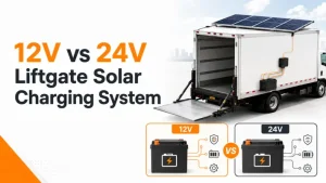
Solar Panel Amps in 12V vs 24V Battery Systems
For the same power level, a higher system voltage generally means a lower current on that side of the system.
A simplified theoretical comparison for 400W is:
| Planning Example | 12V Nominal System | 24V Nominal System |
|---|---|---|
| Power | 400W | 400W |
| Simplified current using nominal voltage | 33.3A | 16.7A |
| Formula | 400 / 12 | 400 / 24 |
These numbers should not be used directly to select a controller, cable, or fuse. A battery does not remain at exactly 12V or 24V while charging. The controller also has efficiency limits, output-current limits, thermal limits, and battery-specific charging settings.
For a more realistic planning calculation, use the expected battery charging voltage rather than only the nominal label. If a 400W controller output were theoretically delivered at 14.4V:
“`text 400W / 14.4V = 27.8A “`
At 28.8V:
“`text 400W / 28.8V = 13.9A “`
Real charging current may be lower because available PV power changes and the controller, cables, battery, and operating conditions introduce losses or limits.
Panel Current Is Not the Same as Battery Charging Current
This distinction is essential when matching solar panels, batteries, and charge controllers.
On the PV side:
“`text PV power is approximately array Vmp x array Imp “`
On the battery side:
“`text Charging power is approximately battery charging voltage x controller output current “`
An MPPT charge controller can accept a higher-voltage PV input and charge a lower-voltage battery. Victron’s official manual describes this directly: the controller can charge a lower nominal-voltage battery from a higher nominal-voltage PV array and will regulate battery charging current up to its rated limit.
Consider an idealized example:
- PV input: 40V at 10A, or approximately 400W
- Battery charging voltage: 14.4V
- Theoretical battery-side current before losses or controller limits: approximately 27.8A
The panel-side current is 10A in this example, but the battery-side current could be higher because the controller converts voltage and current while transferring power. This is why module Imp must not be copied directly into the battery charging-current field of a system design.
Series vs Parallel: What Happens to Volts and Amps?
Module wiring changes the array voltage and current.
| Connection | Approximate Voltage Behavior | Approximate Current Behavior | Main Design Check |
|---|---|---|---|
| Series | Module voltages add | String current remains near the current of one matched module | Maximum string Voc, MPPT operating range, shading and mismatch |
| Parallel | Voltage remains near one module’s voltage | Branch currents add | Input-current limits, cable capacity, connectors, fusing and protection |
Using two matched 20V, 5A modules:
Series Example
“`text Voltage: 20V + 20V = 40V Current: approximately 5A Power: approximately 200W “`
Parallel Example
“`text Voltage: approximately 20V Current: 5A + 5A = 10A Power: approximately 200W “`
These examples assume matched modules under similar conditions. Mixing modules with different electrical characteristics or different shading and orientation can change array behavior and reduce usable output.
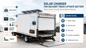
How to Match Solar Panels with an MPPT Charge Controller
The controller must be checked on both the PV-input side and the battery-output side. A wattage comparison alone is not enough.
1. Confirm the Battery Architecture
Record:
- Nominal battery voltage
- Battery chemistry
- Required charging profile
- Permitted charging current
- Battery-management-system limits
- Expected charging temperature range
The charge controller settings must follow the battery manufacturer’s requirements.
2. Collect the Module Electrical Data
For every proposed module, obtain:
- Pmax
- Vmp
- Imp
- Voc
- Isc
- Voltage temperature coefficient
- Maximum system voltage where relevant
- Connector and cable information
If the project uses a customized module, do not assume that the electrical values from a standard model remain unchanged.
3. Define the Series and Parallel Configuration
Calculate the proposed array:
- Series string Vmp
- Series string Voc
- Parallel-array Imp
- Parallel-array Isc
- Total rated PV power
The final values must be compared with the controller’s technical limits.
4. Check Maximum PV Open-Circuit Voltage
The array’s maximum Voc must remain below the controller’s maximum PV input voltage under the coldest expected conditions.
This check cannot use only the datasheet Voc at standard test conditions. PV voltage can rise as module temperature falls. Victron’s installation manual specifically instructs designers to account for both module Voc and its temperature coefficient because Voc will be higher below 25 degrees C.
Exceeding the controller’s maximum PV voltage is not an acceptable operating strategy. The string design should retain the margin required by the applicable equipment instructions and design rules.
5. Check the MPPT Operating Range
The controller needs sufficient PV voltage to begin and maintain charging. The required startup voltage and operating range vary by model.
A string can remain below the absolute maximum voltage yet still operate poorly if its voltage is too low for the controller and battery combination.
6. Check PV Input Current
Parallel strings increase current. Confirm:
- Controller PV input-current limit
- Permitted short-circuit current
- Connector current rating
- Combiner and overcurrent-protection requirements
- Cable ampacity and voltage drop
Use the exact controller documentation because manufacturers may define PV-current limits differently.
7. Check Maximum Battery Charge Current
The controller model name or power rating may not tell the whole story. Confirm its maximum battery output current and ensure that the battery can accept the proposed charging current.
For example, Victron identifies its `75/15` model as having a maximum PV voltage of 75V and a maximum battery charge current of 15A. The two numbers refer to different sides of the controller.
8. Check Permitted PV Array Power
Some controllers allow a PV array with a nameplate power above the controller’s maximum output power and limit or “clip” output under high production. Whether and how this is allowed is manufacturer-specific.
Do not assume that any amount of PV oversizing is acceptable. Check the controller’s permitted PV power, voltage, current, thermal, and warranty conditions.
9. Check Wiring, Protection, and Disconnects
The U.S. Department of Energy identifies batteries, charge controllers, power-conditioning equipment, safety equipment, meters, and instrumentation as typical balance-of-system components in stand-alone renewable systems.
Final wiring and protection should consider:
- Cable ampacity
- Voltage drop
- Connector ratings
- Overcurrent protection
- Disconnects
- Grounding
- Equipment accessibility
- Local electrical requirements
These decisions should be completed by the responsible system designer or qualified electrical professional.
PWM vs MPPT: Why the Current Calculation Changes
PWM and MPPT controllers manage PV input differently.
| Design Question | PWM Controller | MPPT Controller |
|---|---|---|
| PV-to-battery voltage relationship | Usually requires closer voltage matching | Can convert a higher PV voltage to a lower battery charging voltage within its operating range |
| Primary calculation concern | Module and battery voltage compatibility | PV input voltage/current plus battery output current |
| Array configuration flexibility | Generally more limited | Often supports more flexible string-voltage design |
| Does panel Imp equal battery charging current? | Not necessarily | No; input and output current can be substantially different |
| Is one type always better? | No | No; selection depends on system scale, conditions, cost, and equipment requirements |
MPPT is not a substitute for correct string sizing. A controller still has maximum PV voltage, current, power, and battery output limits.
Common Solar Panel Amps-to-Watts Mistakes
Dividing Panel Watts by Nominal Battery Voltage
Using `100W / 12V` gives a simplified battery-side planning number, not the module’s datasheet Imp. Use module Vmp to estimate module current and actual charging voltage to estimate battery-side current.
Using Voc and Isc as Normal Operating Values
Voc and Isc describe boundary test conditions. Use Vmp and Imp for rated maximum-power operation.
Treating Imp as Battery Charging Current
An MPPT controller can convert a higher-voltage, lower-current PV input into a lower-voltage, higher-current battery output.
Ignoring Low-Temperature Voc
Cold conditions can increase module open-circuit voltage and push a series string beyond the controller limit.
Adding Current in a Series String
Series wiring adds voltage. Parallel wiring adds current. Do not reverse these rules.
Assuming Rated Watts Are Constant Field Output
Nameplate wattage is measured under defined test conditions. Field output changes with sunlight, temperature, shading, orientation, soiling, wiring, and controller behavior.
Mixing Modules Without an Electrical Review
Modules with different Vmp, Imp, Voc, Isc, orientation, or shading conditions may not operate together as expected.
Selecting a Controller Without the Datasheets
Descriptions such as “12V panel,” “200W panel,” or “30A controller” do not contain enough information for a reliable system match.
B2B Procurement Checklist
Before requesting a solar module proposal, prepare a system-level RFQ.
| RFQ Item | Information to Provide |
|---|---|
| Application | RV, marine, truck, trailer, portable power station, remote equipment, or off-grid system |
| Target market | Destination countries and applicable documentation requirements |
| Battery | Nominal voltage, chemistry, capacity, charging profile, and maximum charge current |
| Charge controller | Manufacturer, model, MPPT range, maximum PV voltage, PV current limit, output-current limit, and permitted array power |
| Solar array | Target wattage and proposed series/parallel configuration |
| Module parameters | Required Pmax, Vmp, Imp, Voc, Isc, and temperature coefficient |
| Installation area | Maximum length, width, curvature, and available surface |
| Weight limit | Module and mounting weight constraints |
| Environment | Temperature, UV, vibration, moisture, salt exposure, shading, and mechanical stress |
| Cable system | Cable length, connector type, routing, and acceptable voltage drop |
| Protection | Fuse, breaker, disconnect, grounding, and local code requirements |
| OEM scope | Customized dimensions, electrical configuration, branding, packaging, and forecast volume |
This checklist prevents the solar module from being selected in isolation from the controller, battery, wiring, and installation environment.
Where Sungold Solar Panels Fit
Sungold can support the module side of mobile, marine, vehicle, portable, and off-grid solar systems after the system inputs have been defined.
For projects involving curved surfaces, RV roofs, marine installations, lightweight roofs, or customized flexible modules, buyers can review the Sungold PA219 flexible solar panel series.
For projects where reducing module weight is a central design requirement, buyers can review the Sungold PA621 lightweight solar panel series.
The module-selection process should follow this order:
Application and load requirements -> battery architecture -> controller limits -> required PV electrical window -> module format and installation review
Sungold can review module wattage, dimensions, weight, flexibility, installation surface, and project-specific customization requirements. The final controller, battery, cable, fuse, grounding, protection, and complete-system compliance decisions remain the responsibility of the corresponding equipment provider and system designer.
Exact PA219 or PA621 electrical parameters, certification scope, customized configuration, availability, warranty, and project suitability must be confirmed for the selected model before publication in a project specification or purchase order.
FAQ
How do you convert solar panel amps to watts?
Multiply the operating voltage by the operating current. For a module at its maximum power point, rated power is approximately Vmp multiplied by Imp. Use the exact datasheet values rather than the nominal battery-system label.
How many amps does a 100W solar panel produce?
There is no universal value. A theoretical 100W module with a Vmp of 20V would have an Imp of approximately 5A. A 100W module with a Vmp of 25V would have an Imp of approximately 4A. Check the exact datasheet.
How many amps does a 200W solar panel produce?
It depends on Vmp. At 20V, 200W corresponds to approximately 10A. At 40V, it corresponds to approximately 5A. These are formula examples, not product specifications.
Does a 24V solar system use fewer amps than a 12V system?
For the same power, a higher voltage generally corresponds to lower current on the same side of the system. However, use actual operating and charging voltages when sizing equipment, not only nominal 12V or 24V labels.
Is solar panel Imp the same as battery charging current?
No. Imp is the module or array current at its maximum power point. An MPPT controller may convert higher-voltage PV power into a lower-voltage battery output with a different current.
What is the difference between Imp and Isc?
Imp is the current at the maximum power point. Isc is the short-circuit current measured when output voltage is effectively zero. Isc is a boundary parameter, not the normal charging current.
What is the difference between Vmp and Voc?
Vmp is the voltage at the maximum power point. Voc is the open-circuit voltage measured with no connected load. Voc is especially important when checking the controller’s maximum PV input voltage.
What happens to amps when solar panels are connected in series?
For matched modules, series wiring adds voltage while current remains near the current of one module. The string current does not equal the sum of every module’s current.
What happens to amps when solar panels are connected in parallel?
Parallel wiring keeps voltage near the voltage of one module while branch currents add. The controller, connectors, cables, and protection must be rated for the combined current.
How do I calculate MPPT charge controller size?
Confirm battery voltage and chemistry, then calculate array Vmp, maximum cold-condition Voc, Imp, Isc, total PV power, and string configuration. Compare those values with the exact controller’s MPPT range, maximum PV voltage, PV current limits, output-current limit, and permitted array power.
Can a 200W solar panel charge a 12V battery?
Potentially, if the module’s electrical values are compatible with a suitable charge controller and the controller is configured for the battery. Wattage alone cannot confirm compatibility.
What solar panel specifications should OEM buyers provide?
Provide the required Pmax, Vmp, Imp, Voc, Isc, temperature coefficient, dimensions, weight, connector, cable, installation surface, environmental conditions, controller details, battery architecture, documentation requirements, and expected volume.
Final Thoughts
Converting solar panel amps to watts is the easy part. A reliable solar charging system requires the module’s Vmp, Imp, Voc, and Isc to be checked against the battery architecture, charge-controller limits, string configuration, temperature range, wiring, protection, and installation environment.
For B2B buyers, the best next step is to prepare a system-level RFQ rather than request a panel based only on wattage. Once the battery, controller, electrical window, mounting surface, and application conditions are clear, Sungold can review whether a flexible, lightweight, or customized solar module is suitable for the project.