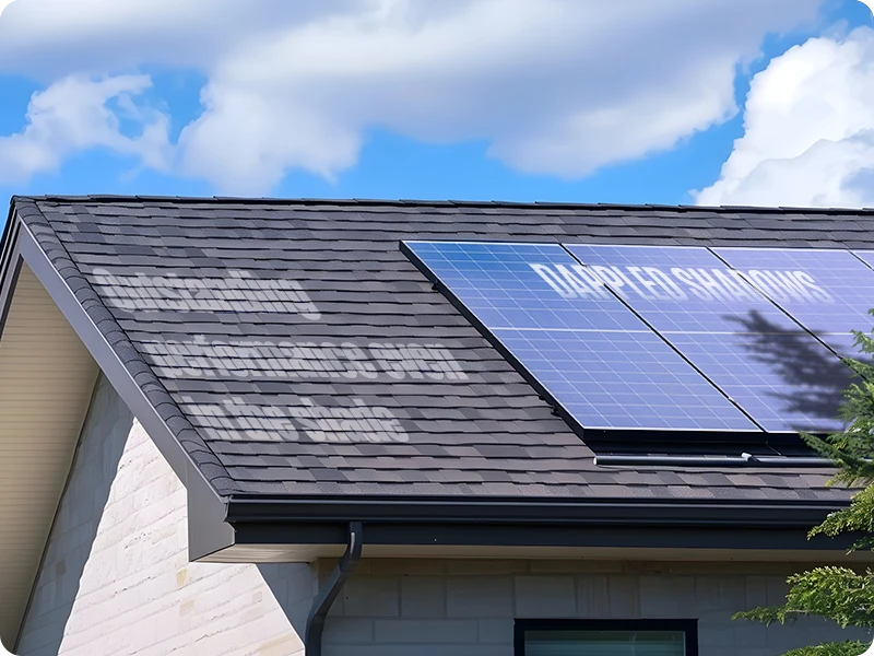


—ENGINEERED FOR PARTIAL & CHANGING SHADE

Anti-Shading Solar Panel for Shade-Critical Applications

Designed for projects exposed to recurring or changing partial shade, Sungold’s Anti-Shading Solar Panel uses an optimized electrical architecture to limit the impact of localized shading and maintain more usable output across the module.

WHAT MAKES THE ARCHITECTURE DIFFERENT?

More Diodes Are Only Part of the Difference

The key difference is how much of the module is managed by each bypass path. With one diode assigned to each half-string, the module is divided into smaller electrical sections, allowing shading effects to be handled more locally.

Distributed Bypass Diodes

Twelve bypass diodes are distributed across the module according to its internal half-string layout.

One Diode per Half-String

Each half-string has its own bypass path, reducing the electrical area affected when localized shading occurs.

Smaller Affected Electrical Sections

Localized shade can be isolated to a smaller electrical section instead of forcing a larger portion of the module into bypass.

Anti Shading Solar Panels

Real Partial-Shading Conditions

Where Partial Shading Occurs in Real-World Applications

In many B2B applications, partial shading is created by the installation environment itself. What matters is not only whether shading occurs, but how frequently, how long, and where it moves across the module.

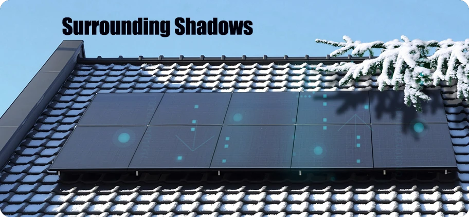
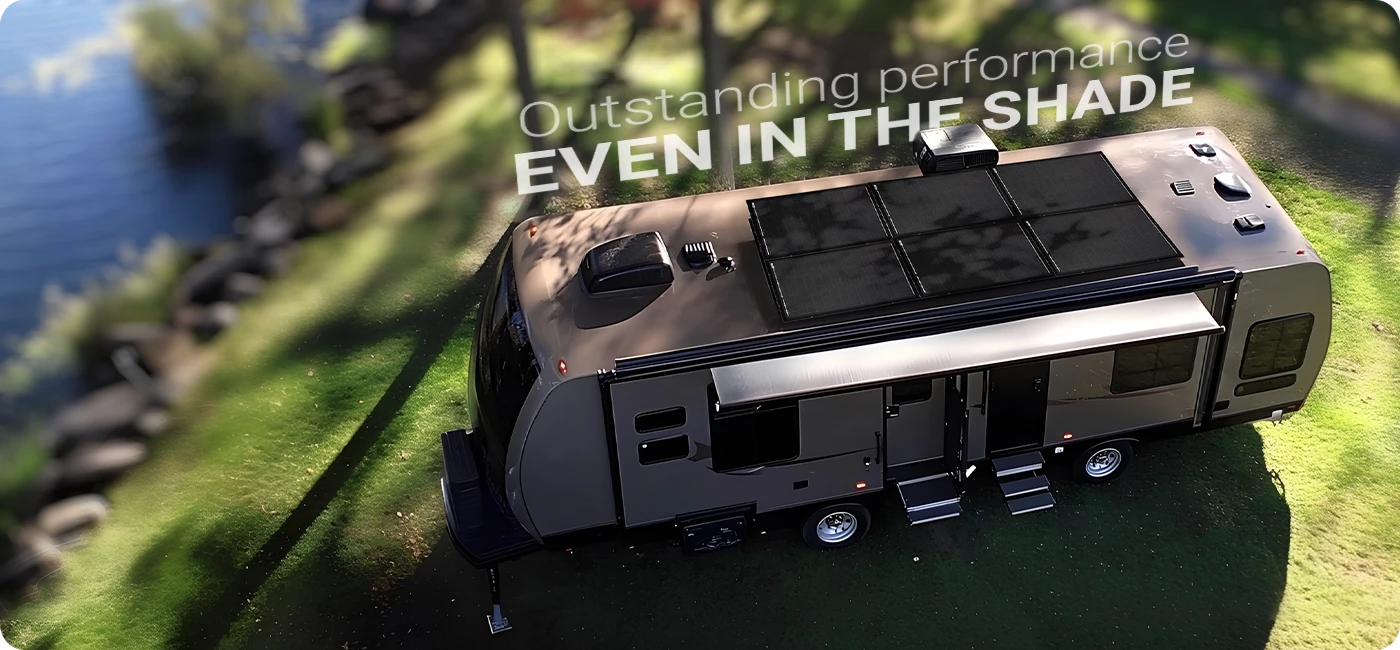
Tree & Branch Shade

Leaves and branches create changing localized shadow patterns.

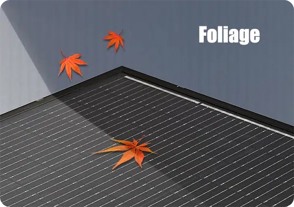
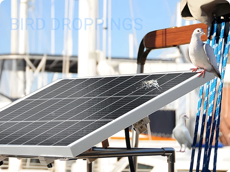
Fallen Leaves

Leaves resting on the module can create localized shading and uneven cell heating.

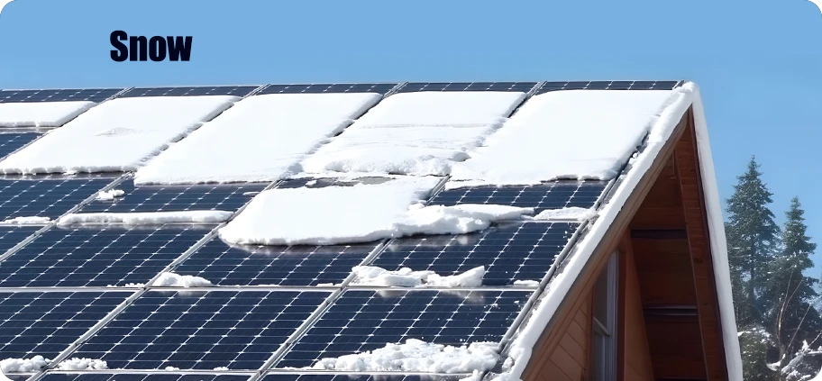
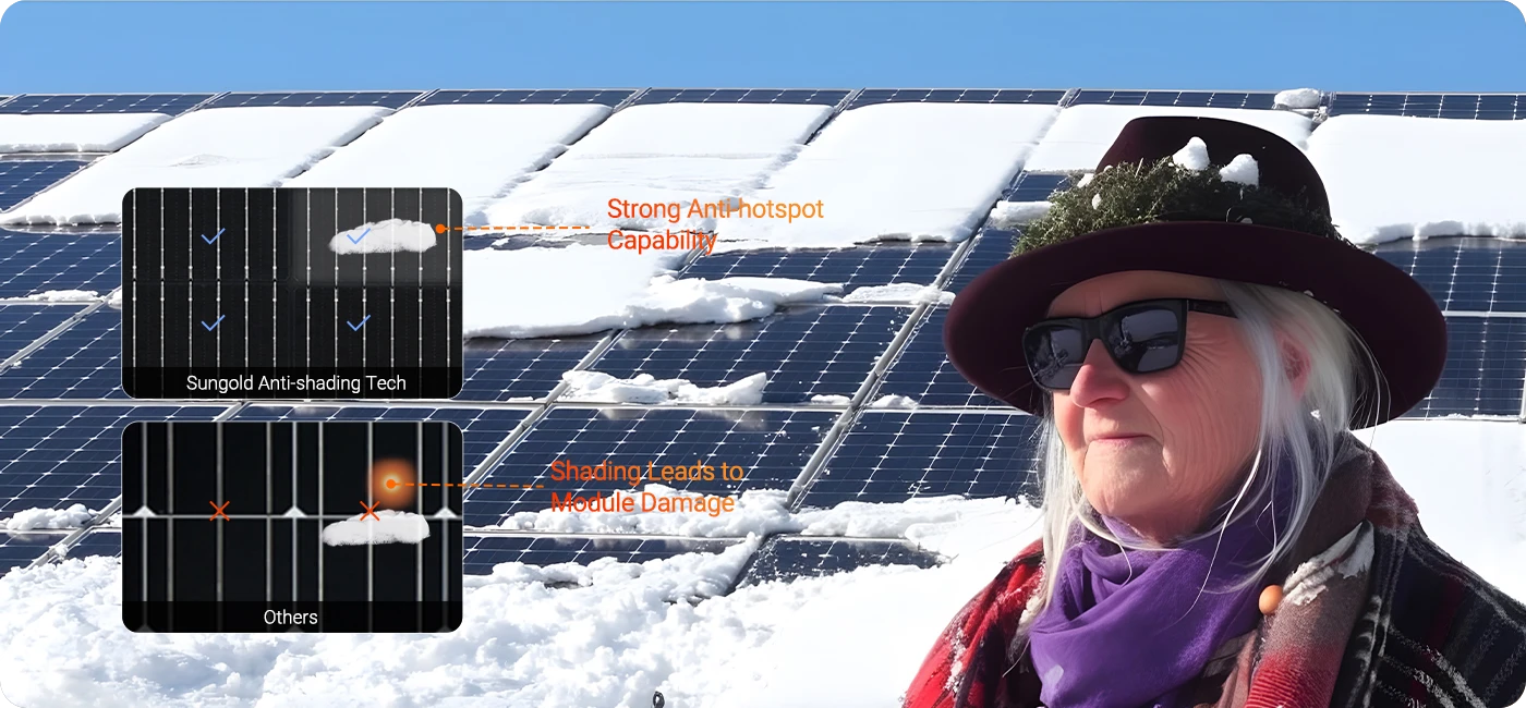
Snow Coverage

Partial snow accumulation can block sunlight and create uneven shading across the module.

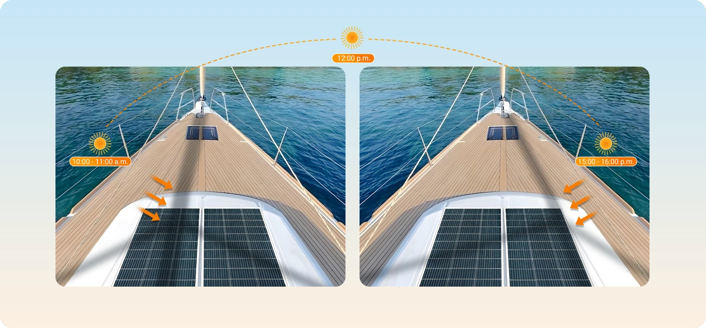
Mast & Rigging Shade

Marine systems frequently experience narrow and continuously moving shadows.

Railing & Building Shadow

Balcony and compact-roof systems may encounter recurring edge shadows.

How the Module Responds to Localized Partial Shading

How It Works

How the Module Responds to Localized Partial Shading

Follow the electrical response from normal operation to localized shading, bypass activation, and continued output from unaffected sections.

Normal operation of Sungold anti-shading solar module Localized shade on Sungold anti-shading solar module Bypass response under localized shade Unaffected solar module sections remain active under localized shading
Normal Operation All half-string sections contribute normally under uniform illumination.

Engineering Value

Engineering Benefits of Anti-Shading Architecture

Finer electrical segmentation helps reduce the impact of localized shading and maintain more active generating area under variable shade conditions.

More Localized Shading Impact

Shading can be confined to a smaller electrical section, reducing unnecessary power loss across the rest of the module.

More Active Generating Area

Unaffected sections can remain electrically active and continue contributing output when localized shading occurs.

Better Suited to Dynamic Shading

Well suited to applications where shadows move, shift, or recur across different parts of the module throughout the day.

Controlled A/B Test Results

Measured Performance vs. a Conventional Solar Panel

Compare the Anti-Shading Solar Panel with a conventional solar panel across four controlled shading scenarios of increasing complexity.

380.3 W

340.4 W average Pmax

vs

382.6 W

Conventional

01 Localized Shade
Test Condition 01

Localized Shade

Small-area shade affecting one local electrical region, representative of leaves, antennas or rooftop accessories.

Matched test set12 positions · 8–9 shaded cells

Average Power Retained

Localized Shade Shows the Clearest Architecture Difference

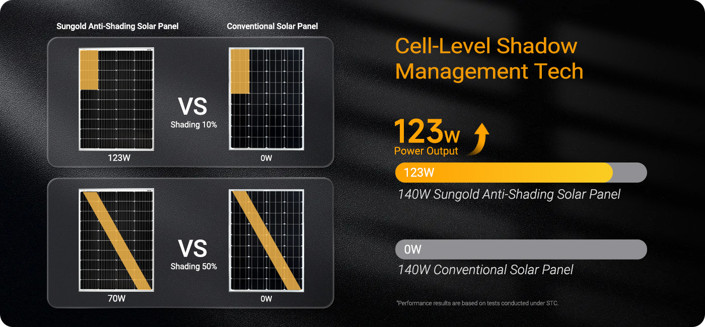
Across 12 matched localized-shade positions, the 12-diode architecture retained substantially more of its unshaded output.

Anti-Shading Solar Panel

89.5%

340.4 W average Pmax

Conventional Solar Panel

30.2%

115.7 W average Pmax

Anti-Shading
0%
Conventional
0%

Anti-Shading Range

88.4–90.6%

Conventional Range

28.4–31.5%

Engineering Takeaway

The response remained highly consistent across all 12 tested localized-shade positions rather than depending on one selected best-case location.

02 Multiple Area Shade
Test Condition 02

Multiple-Area Shade

Two protected regions are shaded simultaneously, representing more than one rooftop or structural obstruction.

Matched test set12 combinations · 17 shaded cells each

Average Power Retained

Stable Retention Across Multiple Shade Combinations

Twelve different region combinations were tested while maintaining the same shaded-cell count in each case.

Anti-Shading Solar Panel

74.6%

283.8 W average Pmax

Conventional Solar Panel

31.6%

120.8 W average Pmax

Anti-Shading
0%
Conventional
0%

Anti-Shading Range

74.0–75.2%

Conventional Range

31.0–32.4%

Engineering Takeaway

Output remained within a narrow range across the different two-region combinations, showing that the measured result was not highly dependent on one specific location pair.

03 Complex Multi Region Shade
Test Condition 03

Complex Multi-Region Shade

Scattered shade affects multiple non-adjacent electrical sections, creating a more severe and irregular electrical condition.

Complex shade set10 patterns · 25–51 shaded cells

Average Power Retained

Complex Shade Creates a More Severe Output Condition

As shade spreads across several separated electrical regions, the architecture difference becomes especially visible in the current test set.

Anti-Shading Solar Panel

29.7%

113.1 W average Pmax

Conventional Solar Panel

0.48%

1.85 W average Pmax

Anti-Shading
0%
Conventional
0%

Anti-Shading Avg. Pmax

113.1 W

Conventional Avg. Pmax

1.85 W

Engineering Takeaway

Under the current complex multi-region test set, the conventional reference dropped to minimal output while the 12-diode architecture still retained measurable usable power.

04 Irregular Tree Shade
Test Condition 04

Irregular Tree Shade

Four different irregular shadow patterns were applied to both architectures to better represent real-world shade geometry.

1
2
3
4
Matched real-world shade set4 irregular patterns

Average Power Retained

Irregular Shading Highlights the Architecture Difference

Across 12 matched irregular-shade positions, the Anti-Shading Solar Panel retained substantially more of its available output than the conventional reference.

Anti-Shading Solar Panel

74.6%

283.8 W average Pmax

Conventional Solar Panel

31.6%

115.7 W average Pmax

Anti-Shading
0%
Conventional
0%

Anti-Shading Range

74.0–75.2%

Conventional Range

31.0–32.4%

Engineering Takeaway

Output remained within a relatively narrow range across different irregular shade patterns, indicating that the performance advantage was not dependent on a single favorable shading position.

Project Evaluation

From Shade Conditions to Module Recommendation

A B2B Anti-Shading project can move from application requirements to technical evaluation, sample validation, and quotation.

STEP 01

Send Project Requirements

Application, layout, shade sources, electrical requirements and estimated quantity.

STEP 02

Technical Evaluation

Review application fit, shading profile, module configuration and system requirements.

STEP 03

Sample / Quote Scope

Confirm technical direction before sample validation, pilot order or quotation.

Tell Us About Your Application

Get an Anti-Shading Project Evaluation

Share your installation layout, expected shade sources, electrical requirements, and target quantity. Sungold can evaluate whether a standard module is suitable or whether an Anti-Shading configuration is more appropriate for the application.

What You Receive

The information you provide helps define the next technical and commercial step.

Application Fit Review

Evaluate whether Anti-Shading architecture is relevant to the installation.

Module Configuration Discussion

Review module size, electrical and installation requirements.

Shade Pattern Review

Consider expected position and movement of recurring shade sources.

Sample / Validation Plan

Define the appropriate next validation step.

Quotation Scope

Confirm technical scope before entering commercial quotation.

FAQ

Anti-Shading Solar Panel FAQ

No. Anti-shading solar panels are designed to reduce and localize the impact of partial shading, not eliminate all power loss. Actual output depends on the shade pattern, shaded area, irradiance, module layout, installation angle, surface condition and MPPT behavior. In Sungold’s supplied controlled comparison, the anti-shading configuration retained approximately 89.52% output under one tested single-region shade condition, compared with approximately 30.23% for the conventional reference configuration. These figures apply only to the stated test setup and should not be treated as a universal field guarantee.

No. “One diode per cell” is not an accurate description of the supplied Sungold test configuration. The anti-shading design uses bypass protection across smaller cell or half-string sections. In the supplied configuration, one diode is used for each half-string, with 12 diodes in total. The conventional reference module uses three junction-box bypass diodes, with each diode covering two larger string sections. The exact electrical topology depends on the product model and should be confirmed in the technical datasheet.

Smaller bypass sections can reduce the number of active cells affected when one area of a module is shaded. This allows the bypass response to be more localized instead of affecting a larger section of the panel. However, the result depends on the shade geometry, electrical layout, irradiance and operating point. A smaller protected section improves shade tolerance, but it does not guarantee full rated output under every shading condition.

A shaded cell does not produce the same current as an unshaded cell. Depending on the shade pattern, the bypass path may not activate in the expected way, and the module may operate at a different point on its I-V or P-V curve. Distributed shade, narrow shadows, dirt, poor orientation and system-level mismatch can all reduce output. Anti-shading architecture mitigates these effects, but it does not make the module completely shade-proof.

Anti-shading solar panels still require a compatible charge controller, MPPT or microinverter. Because finer bypass segmentation can create a more complex I-V or P-V curve under shade, buyers should check the operating voltage range, MPPT window, startup voltage, current limit and tracking behavior of the connected equipment. Sungold can review panel-level requirements, while final system design should be confirmed by the system brand or a qualified technical team.

Anti-shading solar panels are most useful where partial shade is difficult to avoid. Typical applications include RV and vehicle roofs with vents or roof accessories, balcony systems affected by railings and nearby buildings, marine decks with moving equipment shadows, and off-grid installations near trees or structures. The design is most valuable when the shade pattern is repeatable and the module voltage, current and dimensions match the target system.

They can be suitable, but the module should be evaluated together with the microinverter and installation conditions. Buyers should confirm the panel’s Vmp, Voc, Imp and Isc against the microinverter’s MPPT and input limits. Mounting angle, local electrical requirements, cable routing and balcony shade patterns should also be reviewed. Anti-shading performance does not replace local compliance checks or correct system matching.

Do not compare products by diode count alone. Ask for the diode placement, protected section size, electrical layout, shade-pattern test conditions, I-V or P-V curves, thermal evidence, module voltage range, compatible MPPT equipment and relevant product documentation. A meaningful comparison should use the same module power, irradiance, temperature, shade coverage, shade position and test equipment.

Leave a message

If you are interested in our products and want to know more details, please leave a message here and we will get back to you as soon as possible.


    Scroll to Top