 EN
EN
 Deutsch
 Italiano
 Español
 Français
 日本語
日本語
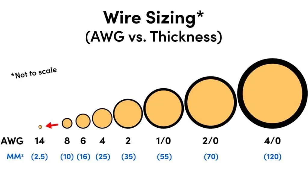
There is no single wire size that fits every solar system. A short 12V battery cable may need to be much larger than a longer PV cable because the current is different. The safest process is to calculate ampacity first, then check voltage drop for the actual cable length.
Wire Size by Cable Run in RV, Marine and Off-Grid Solar Systems
| Cable run | What to check | Why it matters |
|---|---|---|
| Solar panel to charge controller | PV current, string voltage, outdoor rating, and cable distance | Long roof or deck runs can create voltage drop before power reaches the controller |
| Charge controller to battery | Controller output current, cable length, fuse location, and battery voltage | This is often a high-current DC path and should be kept short when possible |
| Battery to inverter | Inverter wattage, surge current, battery voltage, and cable temperature rating | This is usually the thickest cable in an RV or off-grid system |
| Battery to DC fuse block | Total DC load, wire length, fuse size, and acceptable voltage drop | Undersized wire can heat up or cause low voltage at lights, pumps, and electronics |
| Marine bonding or grounding path | Local code, corrosion environment, and system design | Marine installations need extra attention to corrosion, vibration, and safety rules |
12V vs 24V vs 48V Wire Sizing for Off-Grid Systems
Lower-voltage systems carry more current for the same power. That is why many 12V RV and marine systems need thicker cable than a 24V or 48V off-grid system with the same wattage.
| System voltage | Current for 1200W load | Wire sizing implication |
|---|---|---|
| 12V | About 100A before losses | Usually needs short runs, large cable, and careful fuse placement |
| 24V | About 50A before losses | Lower current makes voltage drop easier to manage |
| 48V | About 25A before losses | Often better for larger off-grid systems, but component compatibility must be checked |
When designing electrical systems for RVs, boats, or off-grid solar installations, getting wire-sizing right isn’t optional—it’s critical for safety and performance. Undersized wires can cause:
- Fire hazards from overheating
- Voltage drops that damage batteries and appliances
- Reduced system efficiency and wasted energy
- Insurance claim denials for non-compliant installations
- NEC code violations that fail inspections
This comprehensive guide covers everything you need to know about wire sizing, from understanding the American Wire Gauge (AWG) system to meeting National Electrical Code (NEC) requirements.
Safety Disclaimer: This guide is for educational purposes only. Electrical work can be dangerous and may require permits. When in doubt, consult a licensed electrician. Improper installations can void warranties, insurance coverage, and cause serious injury or death.
Understanding the AWG Wire Gauge System
What is AWG (American Wire Gauge)?
The American Wire Gauge (AWG) system is the standard wire sizing method used in the United States. Understanding AWG is essential for any electrical project.
Key principle: AWG uses an inverse numbering system—the smaller the AWG number, the larger the wire diameter and current capacity.
AWG to mm² Wire Size Conversion Chart
| AWG Size | Diameter (mm) | Cross-Section (mm²) | Typical Ampacity* | Common Uses |
|---|---|---|---|---|
| 4/0 (0000) | 11.68 | 107.2 | 230A – 260A | Large inverters, main battery cables |
| 2/0 (00) | 9.27 | 67.4 | 175A – 195A | Heavy-duty inverter connections |
| 1/0 (0) | 8.25 | 53.5 | 150A – 170A | Main battery feeders |
| 2 AWG | 6.54 | 33.6 | 115A – 130A | Large inverters, alternator charging |
| 4 AWG | 5.19 | 21.2 | 85A – 95A | Medium inverters, solar arrays |
| 6 AWG | 4.11 | 13.3 | 65A – 75A | Charge controllers, DC-DC chargers |
| 8 AWG | 3.26 | 8.37 | 50A – 55A | Solar panels, battery connections |
| 10 AWG | 2.59 | 5.26 | 35A – 40A | Appliance circuits, lighting |
| 12 AWG | 2.05 | 3.31 | 25A – 30A | General circuits, outlets |
| 14 AWG | 1.63 | 2.08 | 20A – 25A | Lighting circuits, low-current devices |
Ampacity values based on 75°C copper wire in free air. Actual values vary with insulation type and installation conditions.
Stranded vs Solid Wire
For RV, marine, and mobile applications, stranded wire is almost always preferred.
| Feature | Stranded Wire | Solid Wire |
|---|---|---|
| Flexibility | High – ideal for vibration and movement | Low – best for fixed runs |
| Vibration Resistance | Better, less likely to fatigue | Poor in mobile applications |
| Routing | Easier through tight spaces | Harder to bend and route |
| Typical Use | RVs, boats, vehicles, battery cables | Homes, buildings, fixed conduit |
Class K Stranding: For battery and inverter cables, look for “Class K” or “welding cable” stranding, which provides maximum flexibility for large gauge wires (2 AWG and larger).
Understanding Circular Mils (CM)
In addition to AWG, you may encounter Circular Mils (CM) in technical specifications:
- 1 Circular Mil = area of a wire with 1 mil (0.001 inch) diameter
- Formula: CM = (diameter in mils)²
- Example: 4/0 AWG = 211,600 CM
MCM / kcmil (Thousand Circular Mils): For very large conductors, kcmil or MCM is used (e.g., 250 MCM = 250,000 circular mils).
Critical Calculations – Ampacity & Voltage Drop
Proper wire sizing requires two separate calculations. You must perform both and choose the larger wire size.
- Ampacity (how much current the wire can safely carry)
- Voltage drop (how much voltage is lost along the wire)
Calculation #1: Ampacity (Current Carrying Capacity)
Ampacity is the maximum current a wire can safely carry without overheating. This is governed by NEC Article 310.
Insulation Types & Temperature Ratings
| Insulation Type | Max Temperature | Common Applications |
|---|---|---|
| THHN/THWN | 90°C (194°F) | General building wire, dry locations |
| THWN-2 | 90°C wet/dry | Conduit, building and RV systems |
| XHHW-2 | 90°C wet/dry | RV and marine applications, underground |
| MTW | 60–90°C | Machine tools, control panels |
| GPT/GXL/TXL | 80–125°C | Automotive 12V systems |
| USE-2 / PV Wire | 90°C | Underground or outdoor solar/PV |
Note: Even if wire is rated 90°C, termination points (breakers, lugs) may be only 60°C or 75°C. You must use the lowest rating in the circuit.
Derating Factors
Real-world installations require reducing the base ampacity.
1. Temperature Correction Factor (for ambient > 30°C / 86°F)
| Ambient Temp | Correction Factor (90°C wire) |
|---|---|
| 31–35°C | 0.96 |
| 36–40°C | 0.91 |
| 41–45°C | 0.87 |
| 46–50°C | 0.82 |
2. Conduit Fill Adjustment (multiple current-carrying conductors)
| Number of Conductors | Adjustment Factor |
|---|---|
| 1–3 | 100% |
| 4–6 | 80% |
| 7–9 | 70% |
| 10–20 | 50% |
Ground wires and some neutrals do not count as current-carrying conductors in these tables.
3. Continuous Load Rule (125% Rule)
For loads running 3+ hours continuously:
Example:
20A DC refrigerator → 20A × 1.25 = 25A required → use 10 AWG or larger.
Ampacity Calculation Example
Scenario: 40A solar charge controller in RV roof (45°C ambient), 2 conductors in conduit
- Base ampacity of 8 AWG @ 90°C = 55A
- Temperature correction: 55A × 0.87 = 47.85A
- Conduit fill: 2 conductors → 100% → 47.85A
- Continuous load: 40A × 1.25 = 50A required
Result: 8 AWG is insufficient (47.85A < 50A).
Solution: Use 6 AWG (ampacity after derating ≥ 50A).
Calculation #2: Voltage Drop
Voltage drop is the loss of voltage between power source and load due to wire resistance.
Too much voltage drop can cause:
- Poor battery charging
- Dim lights and weak appliances
- Extra heat and wasted energy
- Shorter battery life
NEC Voltage Drop Recommendations
| Circuit Type | Recommended Max Voltage Drop |
|---|---|
| Branch Circuits | 3% |
| Feeders | 2% |
| Feeder + Branch Together | 5% |
| Solar/Battery Charging (12V/24V) | 1–2% (best practice) |
Low-voltage systems (12V, 24V) are very sensitive:
3% of 12V = only 0.36V drop.
Voltage Drop Formula
Voltage Drop (V) = (2 × Wire Length in ft × Current in A × Resistance per 1000 ft) ÷ 1000
Percentage Drop (%) = (Voltage Drop ÷ System Voltage) × 100
Always use round-trip distance (out and back), so multiply one-way length by 2.
Wire Resistance Table (Copper, 75°C)
| AWG Size | Ohms per 1000 ft | Ohms per 100 ft |
|---|---|---|
| 4/0 | 0.0500 Ω | 0.0050 Ω |
| 2/0 | 0.0795 Ω | 0.00795 Ω |
| 2 | 0.1260 Ω | 0.0126 Ω |
| 4 | 0.2010 Ω | 0.0201 Ω |
| 6 | 0.3200 Ω | 0.0320 Ω |
| 8 | 0.5080 Ω | 0.0508 Ω |
| 10 | 0.8080 Ω | 0.0808 Ω |
| 12 | 1.2840 Ω | 0.1284 Ω |
| 14 | 2.0400 Ω | 0.2040 Ω |
Voltage Drop Calculation Example
Scenario: 3000W inverter on 12V system, 10-foot cable run from battery
- Current = 3000W ÷ 12V = 250A
- Round-trip distance = 10 ft × 2 = 20 ft
Try 2/0 AWG (0.0795 Ω/1000 ft):
V_drop = (20 × 250 × 0.0795) ÷ 1000 = 0.3975V
% Drop = (0.3975 ÷ 12) × 100 = 3.31%
Try 4/0 AWG (0.0500 Ω/1000 ft):
V_drop = (20 × 250 × 0.0500) ÷ 1000 = 0.250V
% Drop = (0.250 ÷ 12) × 100 = 2.08%
Final Choice: 4/0 AWG (better efficiency, lower heat).
The “Bigger Wire Wins” Rule
Always compare:
- Ampacity (safe current)
- Voltage Drop (efficient power delivery)
Choose the larger wire size required by either calculation.
Pro Tip: For critical charging (solar, alternator, DC-DC), aim for 1–2% voltage drop.
Wire Types for Different Applications
Not all wire is created equal. Using the wrong type can lead to failure, safety hazards, or code violations.
1. Automotive Wire (SAE Standards)
Standard: SAE J1128
| Type | Temp Rating | Voltage | Typical Use | Notes |
|---|---|---|---|---|
| GPT | 80°C | 50V | Basic automotive circuits | PVC; stiff in cold |
| GXL | 125°C | 50V | Engine compartments | XLPE; flexible in cold |
| TXL | 125°C | 50V | Weight-sensitive harnesses | Thinner insulation |
| SXL | 150°C | 50V | High-heat / racing | Thick, heat-resistant |
Best for: RV chassis wiring, 12V accessories, under-hood circuits.
Limitations:
- Not tinned → poor in marine environments
- Typically only 50V → not ideal for higher-voltage PV strings
- PVC insulation may suffer in UV if exposed outdoors
Marine Wire Sizing: Why Tinned Copper Matters
Standard: ABYC E-11 (AC & DC Electrical Systems)
Key Features:
| Feature | Requirement | Benefit |
|---|---|---|
| Conductor | Tinned copper | Corrosion resistance |
| Stranding | Type III (fine strands) | High flexibility & vibration耐性 |
| Insulation | UV, oil, moisture resistant | Long life in harsh marine environments |
| Voltage | Typically 600V | AC + DC compatible |
Common Marine Ratings:
- UL 1426 Marine Wire
- BC-5W2 boat cable (2-conductor, wet locations)
ABYC Color Coding (DC):
| Function | Color |
|---|---|
| DC Positive | Red |
| DC Negative (small boats) | Black |
| DC Negative (large vessels) | Yellow |
| Ground / Bonding | Green or Green/Yellow |
3. Solar PV Wire
Standards: UL 4703, USE-2
| Type | Voltage Rating | Typical Use | Notes |
|---|---|---|---|
| PV Wire | 600–2000V DC | Exposed array wiring | UV & weather resistant |
| USE-2 | 600V | Underground or outdoor PV | XLPE insulation |
| THHN/THWN-2 | 600V | In conduit only | Not for direct sun exposure |
Best for: Rooftop solar, off-grid arrays, charge controller inputs.
Important: Exposed PV conductors must be PV wire / USE-2 (UV-rated), not ordinary building wire.
4. Battery Cable & Welding Cable
| Type | Flexibility | Typical Size Range | Use Case |
|---|---|---|---|
| Welding Cable (Class K) | Extremely flexible | 2 AWG – 4/0 | Inverter & battery cables |
| SGT Starter Cable | Medium | 4 AWG – 1/0 | Starter / ground leads |
| Marine Battery Cable | Flexible, tinned | 4 AWG – 4/0 | Boat & RV battery systems |
Installation tips:
- Keep runs short
- Use crimped, properly sized lugs
- Support every 12–18 inches
- Avoid tight bends and sharp edges
5. Building Wire (NEC Article 310)
| Type | Environment | Pros | Cons |
|---|---|---|---|
| THHN/THWN-2 | Conduit, dry/wet | Cheap, available | Stiff, not for vibration |
| XHHW-2 | Wet/dry, conduit | Tough, durable | Stiffer than THHN |
Best for: Fixed building wiring, conduit runs, shore/AC systems.
Not ideal for: Battery interconnects, high-vibration mobile circuits.
Overcurrent Protection & Safety Requirements
Proper circuit protection is mandatory.
The 7-Inch Rule (NEC 551.10(E))
The unfused positive battery cable must not exceed 7 inches (180 mm) before reaching the first fuse or disconnect.
| Item | Requirement |
|---|---|
| Location | Fuse/breaker within 7″ of battery positive |
| Applies To | RV house batteries (low-voltage DC) |
| Purpose | Protect unfused cable from short-circuit fire |
Ignoring this rule = major fire risk + possible insurance denial.
Fuse Types and Typical Uses
| Fuse Type | Current Range | Typical Voltage | Best For | Notes |
|---|---|---|---|---|
| ANL | 35–750A | Up to 32V DC | RV main DC, inverters | Common, cheap |
| MEGA / AMG | 100–500A | Up to 58V DC | Battery & large DC loads | Compact bolt-on |
| Class T | 1–1200A | Up to 600V | Large inverters, ESS | Current-limiting, premium |
| MRBF | 25–400A | Up to 58V | Marine battery posts, solar | Weather-resistant |
Fuse Sizing Rule:
Fuse must protect the wire, not just the device:
Fuse ≤ Wire Ampacity
Fuse ≈ 80–125% of expected max load
Example: 3000W 12V inverter
→ ~278–300A continuous
→ 4/0 cable ~260A usable
→ Use 250A Class T fuse (protects cable, still allows surge).
DC Circuit Breakers
| Feature | Pros | Cons |
|---|---|---|
| Resettable | No fuse replacement | Higher cost |
| Act as switches | Easy disconnect | Can age/fail |
| Must be DC-rated | Safe arc interruption | Wrong type is dangerous |
Never use AC-only breakers in DC circuits.
Solar Array Protection (NEC 690.9)
- Protect parallel strings from backfeed faults
- Use inline MC4 fuses or combiner breakers
- Typical string fuses: 10–15A
Example: 3 strings of 10A Isc each → 30A backfeed possible → 15A fuse per string recommended.
NEC Codes & Compliance Requirements
Key NEC Articles
| Article | Scope | Relevance |
|---|---|---|
| 551 | RVs & RV parks | DC systems, fusing, bonding |
| 552 | Park trailers | Seasonal RV-type units |
| 690 | Solar PV systems | PV wiring, OCPD, shutdown |
| 710 | Stand-alone systems | Off-grid PV + storage |
| 406 | Receptacles, GFCI | AC outlets, safety |
Highlights
- 551: 7-inch battery fuse rule, RV panelboard rules, bonding.
- 690: 125% PV current sizing, DC disconnects, rapid shutdown, PV wire rules.
- 710: Off-grid system disconnect and classification.
- 406: GFCI for exterior and wet-location outlets.
RVIA / ABYC / UL
- RVIA: Industry standards for RV manufacturers; impacts wiring layout and labeling.
- ABYC E-11: Marine AC/DC installations; tinned wire, color codes, bonding.
- UL Standards:
- UL 44, 83 → wire types
- UL 4703 → PV wire
- UL 1426 → marine wire
- UL 1741 → inverters, charge controllers
Insurance adjusters often check for UL-listed components after a fire.
Real-World Design Examples
Case Study 1: RV Rooftop Solar System
| Item | Spec |
|---|---|
| Array | 4× 100W (400W total) |
| Config | 2S2P (two strings of two panels) |
| Controller | 30A MPPT |
| System | 12V battery bank |
| Environment | RV roof, up to 50°C |
Array → Controller (PV Side)
- Isc per panel = 6A
- Two parallel strings → 12A
- NEC 125% factor → 12A × 1.25 = 15A minimum
Choose 10 AWG PV wire:
- Ampacity after derating > 15A
- Voltage drop ≈ 2.7% at typical Vmp → acceptable.
Controller → Battery
- Output current: 30A
- Use 8 AWG tinned copper or THHN in conduit
- Voltage drop ≈ 2% (good for charging)
- Fuse: 40A ANL within 7″ of battery.
Case Study 2: Marine Alternator to House Battery
| Item | Spec |
|---|---|
| Alternator | 270A |
| House Bank | 400Ah LiFePO₄ (12V) |
| DC-DC Limit | 100A |
| Distance | 15 ft one-way (30 ft round trip) |
| Environment | 45°C engine room, marine |
Use 1/0 AWG tinned marine cable:
- Ampacity after derating > 100A
- Voltage drop ≈ 1.5% → ideal for charging
Fuse: 125A MRBF at battery.
Case Study 3: Off-Grid 3000W Inverter
| Item | Spec |
|---|---|
| Inverter | 3000W, 6000W surge |
| System Voltage | 12V |
| Battery Bank | 600Ah lithium |
| Distance | 5 ft one-way (10 ft round trip) |
Current:
- Continuous ~278–300A
- Surge ~550–560A
Use 4/0 welding cable:
- Ampacity adequate with surge tolerance
- Voltage drop ≈ 1.25% → excellent
- Fuse: 250A Class T within 7″ of battery.
Common Mistakes to Avoid
| Mistake | What Happens | Fix |
|---|---|---|
| Undersizing for surge | Inverter trips, overheats | Size for surge or use flexible welding cable |
| Forgetting round-trip length | Voltage drop 2× higher than expected | Always double the one-way length |
| Using auto wire on boats | Fast corrosion, failures | Use tinned marine-grade wire |
| Skipping temperature derating | Overheated insulation | Apply NEC correction factors |
| Fuse far from battery | Unprotected cable can burn | Put fuse ≤ 7″ from positive post |
| Mixing wire types | Different aging, confusion | Keep each circuit consistent |
| AC breaker on DC | Breaker may not open, arc risk | Use DC-rated breakers/fuses only |
| Ignoring low temp | PVC cracks in cold | Use XLPE or marine wire for low-temp conditions |
Wire Sizing Calculator & Resources
Online Calculators
- Blue Sea Systems DC Wire Sizing
- Southwire Voltage Drop Calculator
- VictronEnergy Toolkit (app)
Quick 12V DC Wire Size Chart (3% Drop)
| Load (A) | ≤10 ft | 10–15 ft | 15–20 ft | 20–25 ft |
|---|---|---|---|---|
| 10A | 14 AWG | 12 AWG | 10 AWG | 10 AWG |
| 20A | 12 AWG | 10 AWG | 8 AWG | 6 AWG |
| 30A | 10 AWG | 8 AWG | 6 AWG | 4 AWG |
| 50A | 8 AWG | 6 AWG | 4 AWG | 2 AWG |
| 100A | 4 AWG | 2 AWG | 1 AWG | 1/0 AWG |
| 150A | 2 AWG | 1/0 AWG | 2/0 AWG | 3/0 AWG |
| 200A | 1/0 AWG | 2/0 AWG | 3/0 AWG | 4/0 AWG |
| 250A | 2/0 AWG | 3/0 AWG | 4/0 AWG | 2× 2/0 AWG |
Wire Sizing FAQ for RV, Marine and Off-Grid Solar
What size wire do I need for a 12V solar system?
The wire size depends on current, cable length, voltage drop target, and where the cable is used. In a 12V system, even moderate loads can require large cable because current is higher than in 24V or 48V systems.
What wire size should I use from solar panel to charge controller?
Check the solar array current, string voltage, one-way cable distance, and outdoor wire rating. The wire must handle current safely and keep voltage drop within the design target.
What size cable do I need from battery to inverter?
Battery-to-inverter cable is sized from inverter wattage, surge current, battery voltage, cable length, and fuse size. This run is often the largest cable in an RV, marine, or off-grid system.
Is marine wire different from regular copper wire?
Marine wire is commonly built with tinned copper strands and insulation suited for moisture, vibration, and corrosion exposure. For boats and harsh outdoor systems, standard automotive wire may not be the right substitute.
Wire Sizing Done Right
Proper wire sizing makes your system:
- Safe – reduced fire risk
- Efficient – less wasted energy
- Compliant – easier inspections and insurance
- Reliable – survives heat, vibration, and corrosion
- Expandable – room for future upgrades
Golden Rules
- Always calculate both ampacity & voltage drop
- Apply temperature + bundling derating
- Match wire type to environment
- Size fuses/breakers to protect the wire
- Follow standard color codes
- Document your system (diagrams + labels)
- When unsure, choose the next larger wire size
- Get permits / professional help when required